


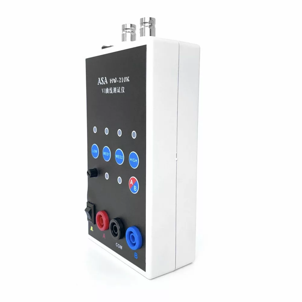


Description
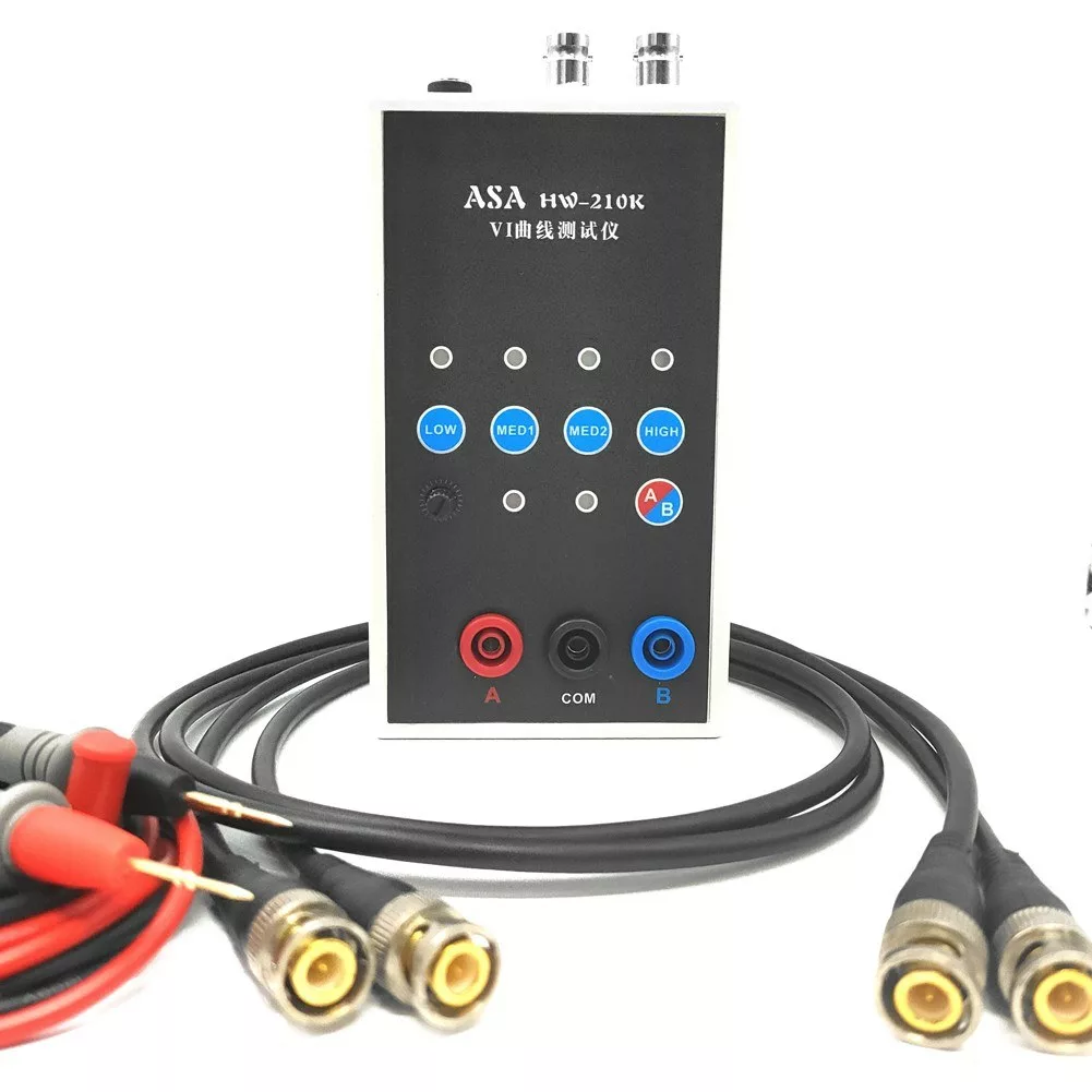
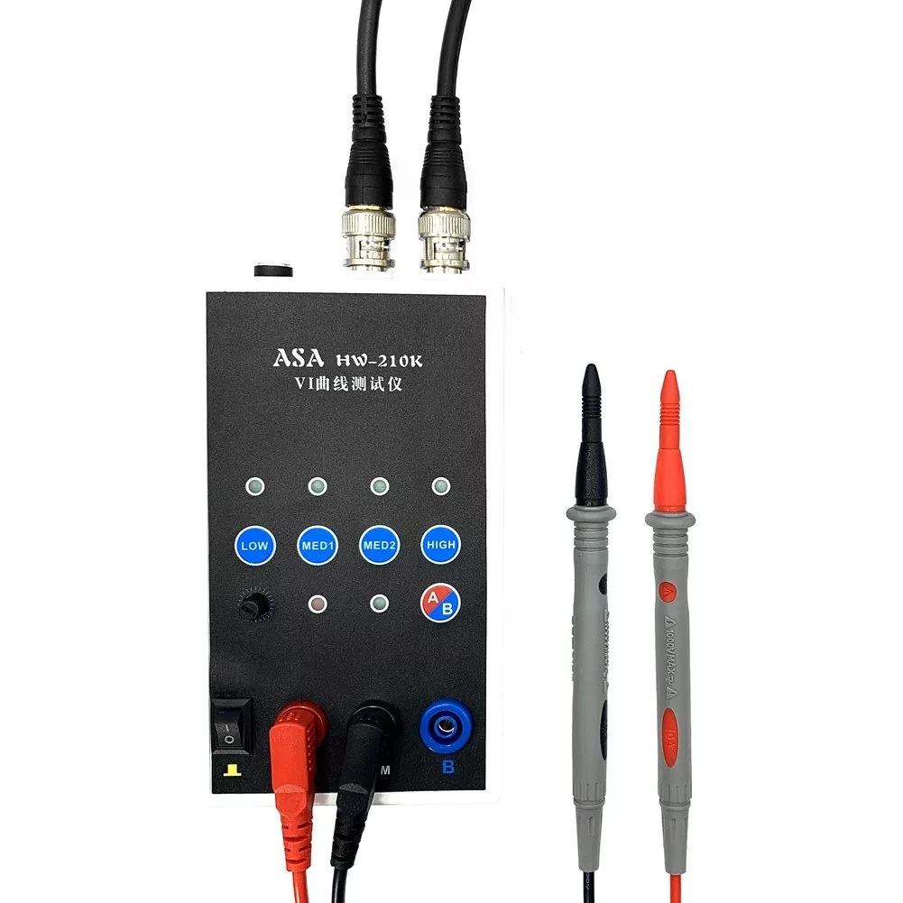
The VI Curve handheld portable tester operates with 4 test frequencies and is designed to be utilized when connected to either analog or digital oscilloscopes.
Features
The VI Curve Tester offers four unique test frequencies and is compatible with both analog and digital oscilloscopes. The dual signal input and alternating display function ensure easy usage. The device offers a 4-gear frequency, along with adjustable alternating speed that can be tweaked to meet specific requirements. The one-click on single channel/alternating display enhances usability. For circuit board testing, avoid recharging the board. If a large capacitor is present on the circuit board, ensure it’s discharged first to prevent damage to the VI test board.
Specifications
Material: plastics
Channel: 2 channels
Frequency: 4 gears
Package size: 195 * 135 * 105mm / 7.7 * 5.3 * 4.1in
Package weight: 435g / 1.0lb
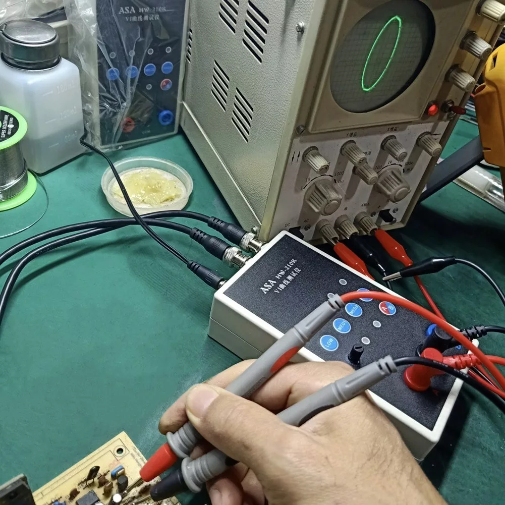
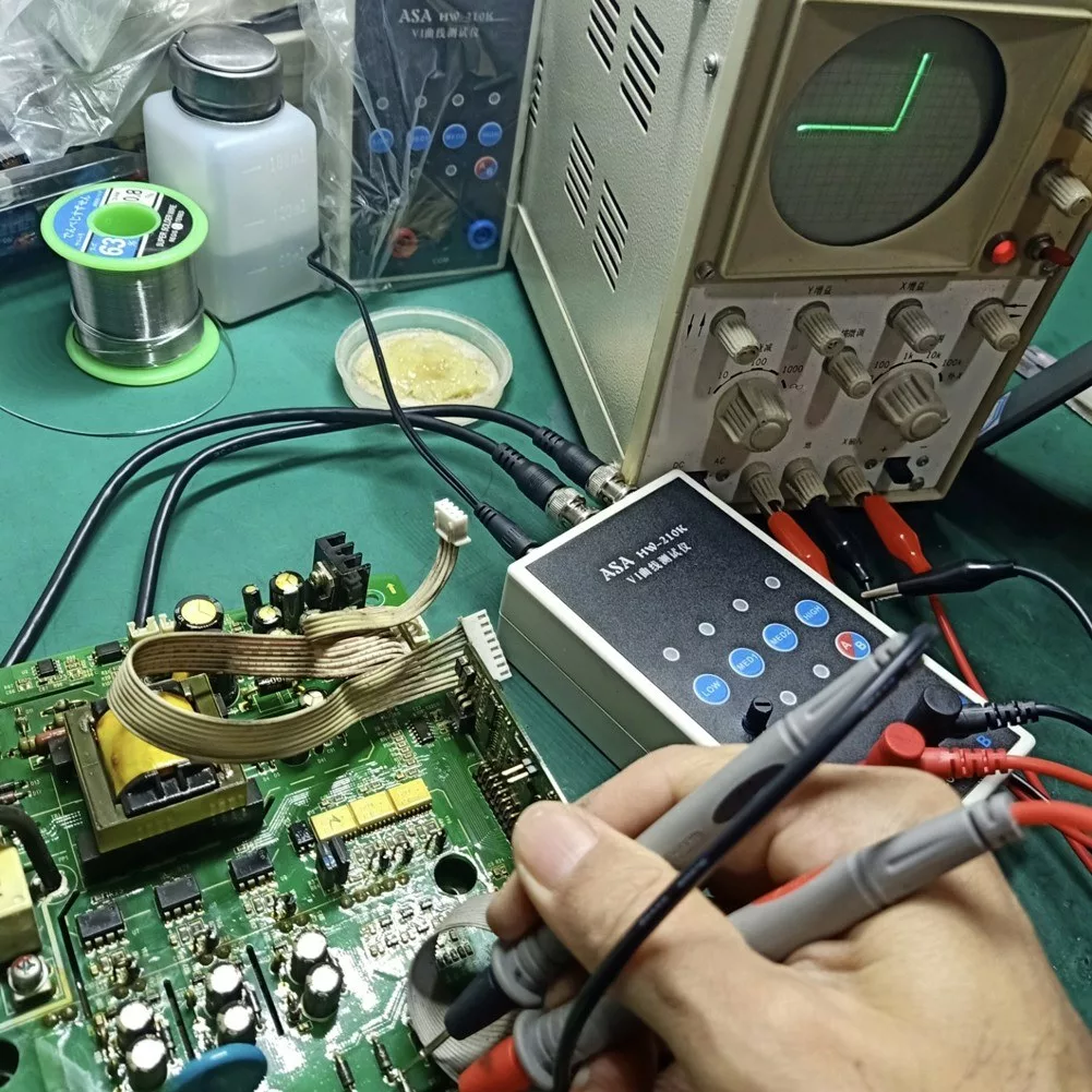
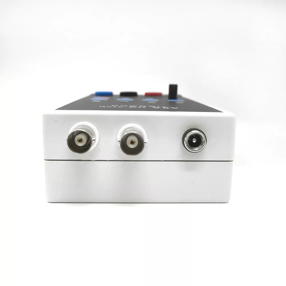
Connecting an Analog Oscilloscope
Adjust the oscilloscope to xY mode. Connect the BNC cable to the oscilloscope and switch it on. Adjust the xY vertical channel parameters to be about 1V/div, with the horizontal line within the display frame. Use the VI test version’s X-attenuation potentiometer to adjust the length of the horizontal line. To display a vertical line, short-circuit the test pen. Adjust the Y channel parameters to center the vertical line within the display frame. Upon achieving correct horizontal and vertical line displays, the device is ready for normal measurement.
Connecting a Digital Oscilloscope
Enter the xY mode via the menu or keys. Adjust the two channels of xY to 1V/div. Set the time base to 1-5 milliseconds, selecting Direct Current coupling for the xY channel, with an attenuation of 1x. Without the oscilloscope connected, the display should show a bright spot which can be centered via the horizontal and vertical adjustments. Connect the VI tester to display a horizontal line. Adjust the potentiometer at the top of the VI board to bring the horizontal line within the display frame. Short-circuit the test leads to display a vertical line. Adjust the Y channel parameters to bring the vertical line within the display frame, effectively completing the debugging process.
Packing list
1 * Tester
1 * Pair of BNC Cable
1 * Pair of Test Cable